وفقا لمعيار ايزو 5658-2 ، فإنه ينطبق على اختبار خصائص السطح من شقة واحدة من المواد ، المواد المركبة أو أجزاء أنبوبي المنتجات المستخدمة على الأسطح المكشوفة من المباني والمركبات ( مثل السفن والقطارات ، وما إلى ذلك ) من خلال تركيب خاص و التثبيت .
1 - نطاق التطبيق :
1-1 تنطبق على اختبار خصائص السطح من شقة واحدة من المواد ، المواد المركبة أو أجزاء أنبوبي المنتجات المستخدمة على الأسطح المكشوفة من المباني والمركبات ( مثل السفن والقطارات ، وما إلى ذلك ) من خلال تركيب خاص و التثبيت .
1-2 وصف وقياس خصائص المواد أو المنتجات أو المكونات في المختبر التي تتوافق مع الحرارة الإشعاعية عند إشعال اللهب .
1-3 خصائص احتراق مواد البناء ومواد القطارات عالية السرعة ومواد السفن . العلاقة بين انتشار اللهب بالجو ، سرعة انتشار اللهب أمام تدفق الإشعاع الحراري
1-4 الأساس ايزو 5658-2 الجزء 5 سطح اختبار القابلية للاشتعال ( سطح المواد الرئيسية تغطي سطح السفينة اختبار ) و متطلبات المنظمة البحرية الدولية res653 . . . . . . . طريقة الاختبار القياسية لتحديد انتشار اللهب أفقيا على الطائرة العمودية تقييم خصائص الاحتراق الرأسي شنت اختبار الكائنات . وقت الاشتعال و إخماد اللهب في كل مسافة سجلت معدل انتشار اللهب كان محسوب و تدفق الحرارة الحرجة CFE ( كيلوواط / متر مربع ) تم قياسها .
2 - الامتثال للمعايير :
2-1 الامتثال ايزو 5658-2 : 2006 رد فعل اختبار الاحتراق - انتشار اللهب - الجزء 2 : انتشار أفقي عمودي بناء ونقل المنتجات .
2-2 الامتثال لقرار المنظمة البحرية الدولية A.653 ( 16 ) من بروتوكول نقل الملفات : " توصيات بشأن إجراءات اختبار مقاومة للحريق من أجل تحسين القابلية للاشتعال من سطح الحاجز والسقف سطح السفينة مواد التشطيب " .
2-3 الامتثال لمتطلبات الجزء 5 من المدونة الدولية 2010 تطبيق إجراءات اختبار مقاومة للحريق ( بروتوكول نقل الملفات 2010 القواعد ) ، سطح اختبار القابلية للاشتعال ( سطح المواد الرئيسية سطح الطلاء اختبار ) .
طريقة الاختبار القياسية لتحديد مستعرض انتشار اللهب من المنتجات الإنشائية و تجهيزات رأسية
3 . السمات الرئيسية :
3-1 واجهة التحكم في الكمبيوتر : واجهة صارمة ، ودرجة عالية من التشغيل الآلي . جميع الإجراءات المعقدة والحوسبة المتكاملة في جهاز الكمبيوتر ، استجابة سريعة جدا ، عملية مريحة ، واجهة ودية ، عملية الحد الأدنى ، وتحسين آلية الأمن ، والبرمجيات يمكن أن تنتج وفقا لمتطلبات المشترين .
3-2 اعتماد المجلس التشريعي الفلسطيني البرمجة ، 16 بت عالية الدقة المجلس ، والسيطرة على جهاز الكمبيوتر . في السيطرة على عملية الاختبار ، اختبار البيانات يمكن أن ينظر إليه في الوقت الحقيقي ، وظائف التلقائي جمع البيانات وتجهيزها ، التلقائي تخزين البيانات ، التلقائي الناتج وطباعة نتائج القياس يمكن أن تتحقق .
3-3 اقتناء نظام يمكن جمع وتسجيل وقت الاشتعال و إخماد اللهب في كل مسافة من العينة ، وحساب معدل انتشار اللهب ، واختبار تدفق الحرارة الحرجة CFE ( كيلوواط / متر مربع ) عند اختبار إخماد ، وغيرها من توليد المنحنيات أو رسم الخرائط . يمكنك حفظ وطباعة ورسم المنحنيات ، والرسوم البيانية ، في الوقت الحقيقي البيانات من جميع العمليات من أجل تحليل
3-4 استخدام المستوردة العسكرية عمود الحرارة مقياس الجريان ، مجهزة المحمولة نظام تبريد المياه . قياس مدى ( 0 ~ 100 ) كيلوواط / متر مربع ، دقة 0.1kw ، مجهزة المحمولة جهاز تبريد المياه .
3-5 المسامية معايرة لوحة انزلاق مقياس الجريان السكك الحديدية المتنقلة المقدمة لتحديد ما إذا كان تدفق الإشعاع الحراري يتوافق مع المتطلبات القياسية .
3-6 لوحة إشعال إشعال التلقائي فتح النار ، ورصد ما إذا كان أو لم يكن اللهب تنطفئ مع المزدوجات الحرارية .
3-7 مع قابل للتعديل مرآة الرؤية الخلفية ، سرعة انتشار اللهب يمكن ملاحظتها من خلال الزجاج مرآة عينة أشعل النار أثناء الاختبار ، ويمكن تسجيلها تلقائيا من قبل دواسة التبديل .
3-8 مجهزة 16 مليون بكسل عالية استيراد اتفاقية مكافحة التصحر ، كامل عملية الاحتراق المراقبة عن بعد والتصوير الفوتوغرافي .
3-9 مراقبة وتحليل مجلس الوزراء تعتمد على تقسيم مجلس الوزراء تصميم .
3-10 اسطوانة المحرك يدعم معيار المنظمة البحرية الدولية التلقائي اختبار تأثير اللهب .
4 - بارامترات الأداء الرئيسية :
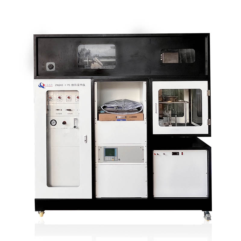
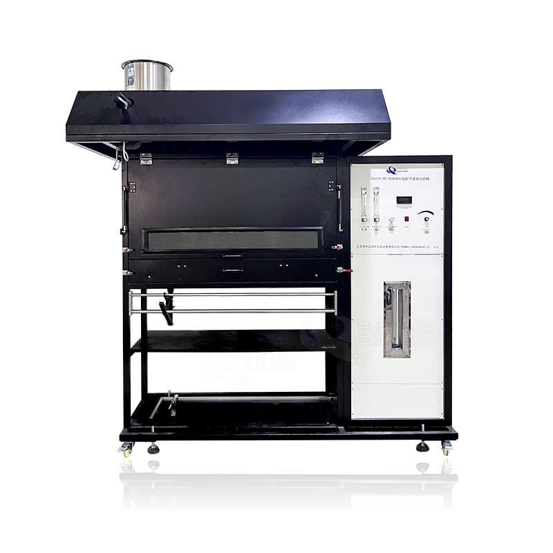
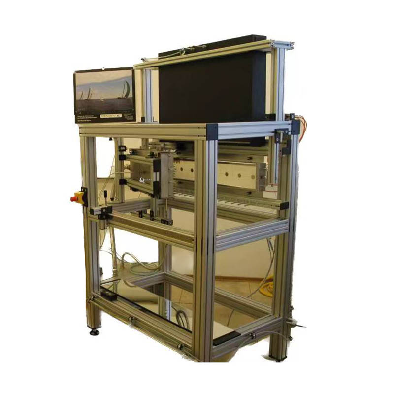
4-1 الصك يتكون من مجلس الوزراء التحكم ، اختبار الجهاز ، الكمبيوتر ، تدفق الحرارة متر معايرة الجهاز ، نظام العادم .
4-2 جهاز تجريبي يتكون من لوحة قوس ، قوس عينة ، أنبوب عينة حامل . حيث ، والإشعاع لوحة قوس متصل مع عينة قوس .
4-3 لوحة قوس الإشعاع : يتكون من أنابيب الصلب الإطار ، لوحة الإشعاع و العرض الجوي .
4-3-1 أنابيب الصلب الإطار : إطار من الصلب أنابيب الغاز ذات الصلة مع نظام الأنابيب ، وأجهزة السلامة ، مقياس الجريان ، جنبا إلى جنب مع دعم لوحة مشع . أنابيب الصلب الإطار يتكون من مربع أنابيب الفولاذ المقاوم للصدأ مع شريحة من 40mm * 40mm ، وتستخدم لدعم يشع لوحة . مركز ارتفاع الإشعاع لوحة ( 1200 ± 100 ) ملم ، والإشعاع هو وضعه عموديا . زاوية بين السطح و السطح الأمامي من إطار من الصلب ( 15 ± 3 ) .
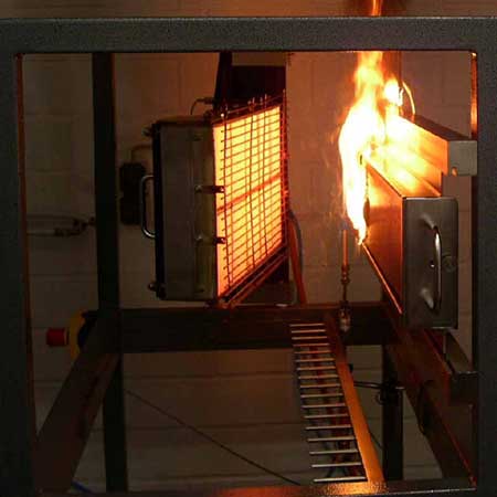
4.4 مصدر الإشعال : لوحة مشع والبروبان الشعلة :
4-4-1 لوحة مشع : يتكون من مسامية الطوب الحراري ، والتي يتم تركيبها بشكل موحد على سطح مشع ، وحجم 450mm * 300mm . تهوية غرفة تقع في الجزء الخلفي من سطح مشع يتكون من يربك لوحة توزيع الغاز الأنابيب المستخدمة في نقل الغاز / خليط الهواء بسلاسة ، ومراقبة تدفق مشع من خلال تعديل كمية الاحتراق . قبل التشعيع على سطح الشاشة لزيادة الإشعاع ، كثافة الإشعاع يمكن أن تصل إلى حوالي 62kw / m2 ، درجة الحرارة السطحية يمكن أن تصل إلى حوالي 750 درجة مئوية . تدفق الحرارة قياس الإشعاع لوحة مريحة ، والمسافة بين المسارات هو 50 ملم .
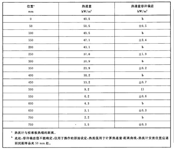
4-4-2 تدفق الحرارة من لوحة مشع تطبيقها على عينة انخفضت بشكل متدرج على طول الجانب الطويل من العينة ، بدءا من 50 كيلوواط / م ² ، ونهاية 1.5 كيلوواط / م ² . تدفق الحرارة القيم تتفق مع الجدول أدناه .
4-4-3 التحكم في درجة الحرارة من لوحة مشع : التحكم في درجة الحرارة من لوحة مشع ، أي تدفق الحرارة الإشعاعية ، عن طريق ضبط سرعة تدفق الهواء من خليط الغاز والهواء . صمام الملف اللولبي يمنع اللهب من الانتقال إلى الجزء الخلفي من المبرد ، والتحقق من درجة الحرارة داخل المبرد ، تلقائيا اغلاق الغاز عند اللهب يعود .
4-4-4 الشعلة : الشعلة من البروبان الشعلة هو 80mm طويلة ، والتي يتم تطبيقها على العينة في 20mm بعيدا عن حافة الإشعاع لوحة .
4-5 نظم الإمداد بالغاز :
4-5-1 الإمداد بالغاز : يمكن تحقيق الإمداد بالغاز والهواء اللازمين للاختبار عن طريق تنظيم منظم تدفق الضغط ، ومعدات الحماية ، ونظام التحكم في التدفق . حلقة الهواء يتم توفيرها مع صمام تخفيض الضغط ، صمام الضغط صفر ، هدأ صمام ، صمام الملف اللولبي ، صمام تنظيم ، خلاط ، وما إلى ذلك الهواء مختلطة والغاز يتم نقلها إلى الإشعاع لوحة .
4-5-2 معدل تدفق الاحتراق : 10 لتر / دقيقة ~ 100 لتر / دقيقة .<1%.<>
4.5.3 Gas: more than 95% propane.
4.5..4 Air flow: 100L/min~1000L/min. Error<1%.<>
4.5.5 Air supply: provide air for the high-pressure air compressor, and have specific flow control valves, air filters and air dryers.
4.5.6 The air and gas supply valves are independently controlled.
4.5.7 To prevent backflow of gas, check valves and pressure regulators are installed on gas pipelines.
4.5.8 In case of abnormal conditions, such as power outage, pressure outage and reduction of combustion surface temperature, the solenoid valve of the gas pipeline can be automatically closed.
4.6 Sample holder:
4.6.1 The sample support includes guide rails, igniters, mirrors and observation grade marks, where the guide rails are used to support the sample holder and place the sample holder in a specific position.
4.6.2 Steel pipe frame: composed of square steel pipes with a section of 40mm×40mm. It is connected to the bracket frame of the radiation plate through nuts and positioning pieces, and it can adjust the angle between the surface of the radiation plate and the surface of the sample in the range of 120~180.
4.6.3 Sample installation navigation: The sample installation guide rail determines the installation position of the top and bottom edges of the sample holder. The guide rail is made of stainless steel, which can resist heat and corrosion. The lower rail is 700mm long and has a groove on the surface, and the top of the edge of the sample holder should be fixed by one or more plugs. The guide rail is installed from one end of the frame, fixed by steel stud material and nuts, and its corresponding position with the bracket is adjustable.
4.6.4 Observation mirror: length 750mm, width 120mm, the rotation axis is located at the bottom of the bracket opposite the sample fixture, and the observation mirror is located under the radiation plate. Its position and angle should enable the observer to observe the sample and the observation grade mark on the surface of the sample from the observation mirror.
4.6.5 Observation level mark: used to improve the observation accuracy of the flame front. Observation level marking is made of heat-resistant steel material, 700mm long. Nail 100mm long nails on it at intervals of 50mm, and the observation level marks are set from the bottom of the sample fixture guide rail to ensure that the nails are kept level with the front end of the sample line.
4.7 Sample clamp: It is made of steel with a thickness of (3±0.2) mm. The clamp is flexible and can place the sample in an appropriate position. The front edge should have a zigzag edge with a V-shaped mark. The interval between the V-shaped marks is 50mm to facilitate the observation of flame spread. The zero mark corresponds to the vertical edge of the sample near the radiant plate. The number of sample holders is four.
4.8 Pilot burner:
4.8.1 Igniter structure: a double-hole ceramic tube with a length of about 200mm, the diameter of the ceramic tube is about 6mm, and the diameter of each hole is 1.5mm. It is composed of connector, pilot burner bracket, flame controller, pressure reducing regulating valve, flow meter, needle valve, one-way valve, on-off valve, propane gas tank, air delivery pipe, etc.
4.8.2 Pilot burner installation: It is located on the sample holder, and its position corresponds to the surface of the sample to be tested. The mixed gas of propane/air is supplied to the pilot burner through the control valve and flow meter.
4.8.3 Pilot burner gas: propane with a purity of more than 95%.
4.8.4 Flame height: (230±20) mm.
4.9 Linear burner: It consists of a pipe with a length of 2m and an inner diameter of 9.1mm, one end is closed with a pipe cap, and a row of 15 holes with an interval of 16mm and a diameter of 3mm is drilled through the pipe wall.
5. Test environment:
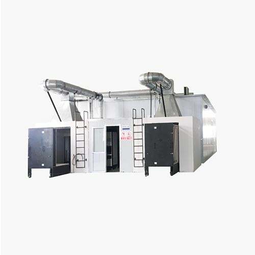
5.1 is a room with a volume not less than 45m3 and a ceiling height greater than 2.5m with a smoke exhaust system. The smoke exhaust system is placed under the ceiling and its discharge capacity is greater than 0.5m³/s.
5.2 Requirements for the exhaust hood: the size of the lower opening of the exhaust hood is 1.3m×1.3m, and the distance from the lower edge to the floor of the room is (1.7±0.1)m. The sample holder and radiant panel are located under the fume hood, so that the combustion fumes are directly removed.
5.3 The testing machine should be placed in an environment without the influence of airflow, and the distance between it and the wall of the test room should not be less than 1m. When the materials on the ceiling, floor and wall are painted with combustible paint, the distance from the radiant heat source should be more than 2m.
5.4 There is an air inlet in the test room. Because there is smoke exhaust, the air in the room should be replenished. When supplying air, the ambient temperature should be controlled within the range of 10°C to 30°C.
5.5 When the smoke exhaust system is running, test the air velocity near the blank sample. At this time, the radiant plate and the air supply system are closed. At a distance of 100mm from the sample, the air velocity perpendicular to the lower edge and the air velocity in any direction in the middle of the sample shall not exceed 0.2 m/s.
6. Test equipment
6.1 Heat flow meter (provided by the buyer): Imported military-grade thermopile heat flow meter is used, equipped with a portable water cooling system. The measuring range is (0~100)KW/ m², and the precision is 0.1KW. The sensing face of the heat flow meter is less than 10mm in diameter and is covered with a durable matt black coating. The radiation receiving target is water-cooled. One is used for testing and the other two are used as reference standards. Non-linearity ±2%, repeatability ±0.5%.
6.2 Timer: visual resolution: 0.1s, timing error: 1s/1h
6.3 Data collection: Taiwan Advantech boards, different types of transmitters, differential pressure gauges, and wide-angle full-radiation pyrometers are used, and the collection frequency is automatically recorded every 3s.
6.4 Blank sample: used to adjust the thermal radiation value of each point. Made of non-combustible materials (such as calcium silicate board), the density after drying is (950±100)kg/m³, the length is 800mm, the width is 155mm, and the thickness is (25±2)mm. A blank sample is placed in place of the sample and is removed when the test sample is installed.
6.5 Calibration board: It is made of non-combustible materials (such as calcium silicate board), with a density of (950±100) kg/m³ and a thickness of (25±2)mm after drying. There are eight holes with a diameter of 25mm on the calibration plate, and the heat flow meter is inserted into each hole in turn to measure the heat radiation value of each point. The other unmeasured holes of the heat flow meter should be plugged with plugs made of the same material as the calibration plate, and the plugs can be assembled and disassembled.
6.6 The heat flux meter used to measure the radiant flux of the specimen should be an imported heat flux meter with a diameter of 25 mm, the brand is HUKSEFLUX in the Netherlands, and the range is (0-100) kW/m².
6.7 The gas system is equipped with low pressure protection device, Venturi mixer device, solenoid valve, pressure reducing valve and other gas control devices.
6.8 Back plate and positioning sheet: it is a non-combustible plate (such as calcium silicate plate) thick (12.5±3) mm, the size is the same as that of the blank sample, and the density after drying is (950±100) kg/m³. The material of the positioning sheet is the same as that of the backplane, cut into (25±2)mm wide strips, and installed on the edge of the backplane.
6.9 Air flowmeter: Rotameter is used, the range is 0~9L/S.
6.10 Gas flowmeter: use rotameter, the range is 0~1.0L/S;
6.11 Airflow temperature and check the measurement of the internal temperature of the cooling plate. Measured by a sheathed thermocouple with an outer diameter of 1.5mm.
6.12 Ambient temperature measurement in the test room: K-type armored thermocouple with a diameter of 2.0mm.
6.13 Smoke exhaust fan: The smoke exhaust speed is greater than 0.50 cubic meters/S. Power 1.5kw.
6.14 All control systems are safe and explosion-proof.
 WhatsApp:
 تليفون محمول:
 اتصل الآن